Introduction

The First OSCAR-5 Run tutorial gave you an overview of the system and the modelling capabilities in OSCAR-5. This tutorial will focus in greater detail on how to build a reactor model in OSCAR-5 and then the next tutorial (Full Core Applications) will pick up where this one ends and use a reactor model to do some real life applications such as corefollow calculations. This tutorial is split into two parts, the first part will cover building the detailed reactor model, while the second part, Mini Core Part 2, will cover the creation of a nodal model.
Background
In this tutorial you will learn how to build a reactor model, starting with nothing but the engineering specifications, and ending with a unified, code-independent, detailed heterogeneous reactor model. You will further learn how to deploy your reactor model to target codes for a few specific calculations. The focus of this tutorial will be on model building and verification and validation of the model.
Attention
- After this tutorial, you will be able to…
Start from scratch and create a reactor model in OSCAR-5.
Create fuel, control, reflector, irradiation rig assemblies and a pool facility in OSCAR-5, from reactor specification documentation.
Create a reactor configuration in OSCAR-5 for a mini core design.
Define the reactor state and loading at first start-up.
Perform a rod worth calculation with Serpent.
The Scenario
Your facility is investigating different reactor design ideas. A mini core has been defined for this study. You have been given specification documents and have been tasked with creating the calculational model for this reactor design. This design is unique and therefore you have no previous models to start with, you will have to build the components and core configuration from scratch. Since this is a conceptual study, you can suffice with simplified assembly models, thereby not getting lost in the detail at such an early stage of the study.
You decide to create both a Serpent model and a nodal model of the reactor. You will test the accuracy of your nodal model by quantifying the errors introduced at each stage of construction, ending with an expected accuracy for your final 3D full core nodal model as compared to the reference heterogeneous 3D full core Serpent model. Finally you will do a rod worth calculation with both models, to confirm whether your nodal results have the accuracy that you predicted.
The mini core model description
The reactor that we intend to model, which we will refer to as the mini core, has a small core with a regular 3x3 grid of rectangular assemblies. It contains seven plate-type MTR fuel assemblies surrounding a follower type control rod, with an in-core irradiation facility in the bottom right corner. The core is moderated and reflected with light water, and has an extra block of beryllium North of the core for additional reflection. A top view of the reactor is shown in the next figure. The irradiation target that will be loaded into the rig is a cube of natural cobalt.
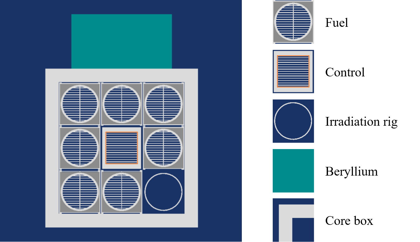
Top view of the mini core reactor, showing the beryllium reflector, core box, fuel and control assemblies, and the empty irradiation facility
The MTR fuel is made up of 19 plates and contains uranium-silicide fuel enriched to 19.75 %. The control rod has a fuel follower with 15 plates of the same design as those of the standard fuel, as well as a rectangular tube of cadmium encased in aluminium and filled with water as the absorber section. The absorber section is 79.53 cm long, and the rod has a travel distance of 74.79 cm. The active region of the core is 59.37 cm high. All the assemblies slot into a grid plate at the bottom of the core.
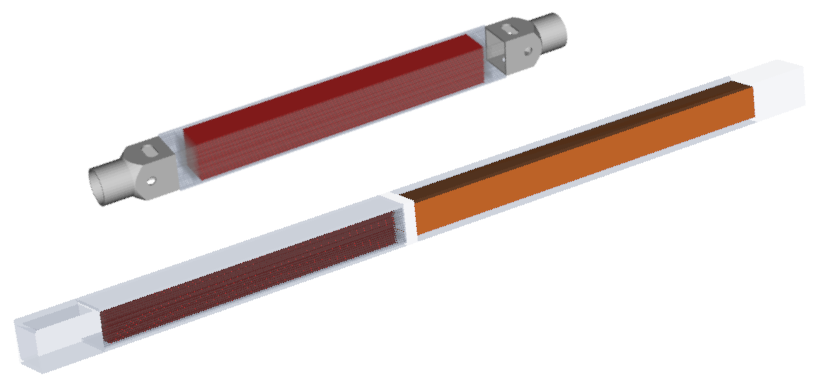
Plate-type fuel and follower control assembly. Red indicates the fuel and orange indicates the cadmium absorber.
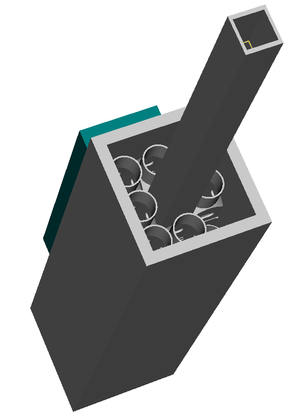
Isometric view of the reactor
These two figures show the fuel and control assemblies with some of their structural materials made transparent in order to expose the neutronically active parts of the assemblies. Also the full reactor with all components and the control rod fully extracted in an isometric view.
All information needed to model this reactor is contained in the OSCAR-5 model description for this tutorial (Tutorial found here), when you open model_description.html on top-level. This documentation describes all components and the core configuration for the mini core and includes detailed CAD drawings of all these components. The documentation was auto generated by OSCAR-5 directly from model input, thereby ensuring consistency between the model and the documentation. This is a very useful feature of the code , and will be addressed in the Step-by-step section of this tutorial. The specifications for the fuel assembly, control rod and irradiation rig were taken from the SAFARI-1 benchmark, but their full descriptions are available in the model documentation.
The OSCAR Approach
In OSCAR-5 you can approach the task of building a reactor model in many different ways. In this tutorial we will outline one way of doing so that conforms to the best practices in using, and especially getting started with, the system. The last part of this section will describe the conceptual mini core that you will be building.
It is also possible to import large parts of the model from an existing MCNP input deck, if one is available. This can bypass a lot of work, especially if the MCNP model has an established verification and validation basis. This process will not be discussed in this tutorial, but further information is available in the OSCAR-5 user manual. An example of how to use this feature can be found in the model of the SAFARI-1 reactor used in the tutorial Running Corefollow and Related Applications with OSCAR-5.
How to build a unified reactor model
Building a new reactor model from scratch can be a daunting task in any reactor analysis code. Here we will outline the general approach and philosophy for doing so with OSCAR-5, which will allow you to create models in other codes automatically. Before getting started you must, of course, obtain the documents that describe the technical specifications of the reactor you intend to model, and to familiarize yourself with them. A clear understanding of the facility will guide all the decisions an analyst must routinely make when building a reactor model.
The OSCAR-5 system facilitates a methodical, step wise approach to building a new reactor model, which will guide you in planning and creating your model. The first step in this approach is to build a detailed model of each assembly type (including the pool) separately. You should therefore start by extracting all information that relates to individual assemblies from your reactor specification, and group or collate this according to assembly type. The individual assembly models are combined into an assembly archive, which can then be referenced when the full-core configurations are constructed.
With an assembly archive in hand, the next step is to define how those separate components are assembled into a functioning reactor. This involves defining a general core layout, determining the initial fuel loading, configuring control structures, specifying the rest of the reactor systems and loading any irradiation facilities. The flow of this is shown in the next figure.
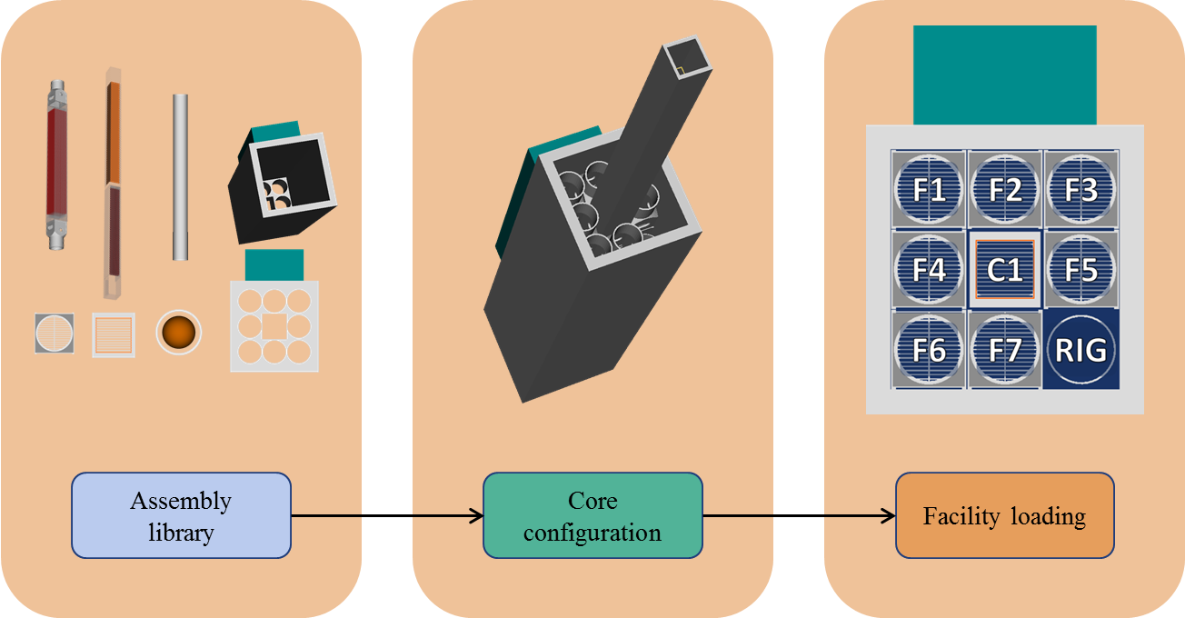
Progression of model construction process
Once such a core configuration and related reactor state is defined, this code-independent unified reactor model can be used for reactor analysis. In this final step you can deploy your model to various reactor analysis codes, and create code specific input for numerous calculational applications such as core-follow, reload, core design and control rod calibration calculations, among others. This procedure is detailed in the following points:
- Plan the component models:
Define a list of components to model. While some of these will simply be fuel or reflector assemblies, the ex-core region also contains components that do not necessarily resemble a standard assembly, and decisions need to be made about how they should be treated.
For each component, decide what its default state is, as well as what other states may apply to it. For example, fuel assemblies are burnable, while irradiation facilities may be empty or have other components loaded into them. Some components may also be removable, or designed to be inserted into other components, also known as loadable components.
- Build an assembly library:
Model the geometry and initial material composition of each component. OSCAR-5 and the Python interface provide several tools to simplify this task, such as macros, an extensive library of built-in geometry constructs, and utilities to support defining material compositions in a number of different units. These tools will be discussed at length in further sections of this tutorial.
Specify the possible changes to the initial geometry and material states by identifying components, commonly referred to as rigs, into which other components, known as targets, may be placed, and defining burnable materials and regions for assemblies that may undergo transmutation.
- Design a base core configuration using the assembly library:
Define the layout of the core, marking the positions that are fixed, and those into which movable assemblies may be placed. At this point, the fixed positions are usually filled with the appropriate assembly type, while placeholders are specified for the rest.
Place the different movable assembly types into the positions they will occupy in the core, for example the places that will contain fuel or inter-assembly control rods.
Group control rods into banks and tag rig positions. The rigs may be loaded with their targets at this stage, but it is more common to do that at the point where the model combined with an application, since rig states are often application dependent.
Set the default state of the core, i.e. moderator density, fuel temperature etc. These may be overridden when the configuration is used subsequently, but it is preferable to have a default defined.
Specify the placement of the structures around the core, including the pool.
- Set the state of the facility at a specific point in time:
Capture the state of the reactor at a specific point in time and associate it with a time stamp.
Define the placement of specific, named, instances of movable assemblies.
- Define applications:
After building the model as described in the preceding steps, use the functionality provided by OSCAR-5 to do calculations with the appropriate calculational tools, as required to support reactor operations. Examples include the modelling of flux measurement experiments, control rod searches and excess reactivity calculations. At this point the model can not be exported to nodal codes, and that calculational tool will only be available after going through the process that will be explained in Part 2 of this tutorial.
Steps 1 to 3 above are typically done only once for a reactor, unless significant changes are made to it. Steps 4 and 5, however, are repeated as necessary to follow and support ongoing reactor operations.
Symbols and Abbreviations
CAD Computer Aided Design
CSG Constructive Solid Geometry
GUI Graphical User Interface
LEU Low Enriched Uranium
MTR Material Testing Reactor
OSCAR-4 Overall System for the CAlculation of Reactors, generation 4
OSCAR-5 Overall System for the CAlculation of Reactors, generation 5
POLX Polynomial cross-section fitting code
SAFARI-1 South Africa Fundamental Atomic Research Installation 1