Background
Introduction
The Rapyds platform is the component of the OSCAR-5 system that provides an interface between the reactor data model and specific simulation tools/codes.
An appropriate simulation solver is chosen depending on the application such as flux calculations, core-follow or reload design as demonstrated in the schematic of the OSCAR-5 system in the Introduction. As an example, a core-follow calculation may be performed with either the MGRAC or Serpent reactor physics solvers. Rapyds generates the input required by the chosen simulation tool, for the application at hand from the code-independent reactor model.
This training manual will guide developers in coupling new simulation tools and applications to Rapyds. It is prerequisite that the reader be familiar with the OSCAR-5 System Overview as well as the OSCAR-5 Usage Training Documentation before proceeding to the rest of this guide.
Back to the specific topic of this training manual, the vehicle for establishing the connection between Rapyds and an external codes is found in the Rapyds Application Framework, which is depicted in
application_frame. This training manual will describe the Application Framework, and demonstrate its use at the hand of a simple example.
We begin by introducing the UML Class diagrams for the Rapyds Application Framework and Rapyds Data Model.
Tip
UML class diagrams are in themselves complex constructs, which indicate how data elements in the system relate to each other. Various type of association between elements can be indicated, such as inheritance (triangle: is a), aggregation (open diamond: combines into complex object), composition (solid diamond: highly dependant relationship) and multiplicity (one-to-many, many-to-many) can be indicated in such diagrams. A deep understanding is not required at this point.
The diagrams below likely appear too detailed and unreadable, but are rendered in high resolution, and clicking upon them would allow deeper investigation of the detail. This is however not needed at this stage.
Note
Classes are grouped together in the UML diagrams into modules (black boxes with titles). These modules map directly onto Rapyds source code modules found in the directory structure of Rapyds. Where multiple boxes are shown within a larger box, the larger box would map onto a Python package in Rapyds (separate folder)
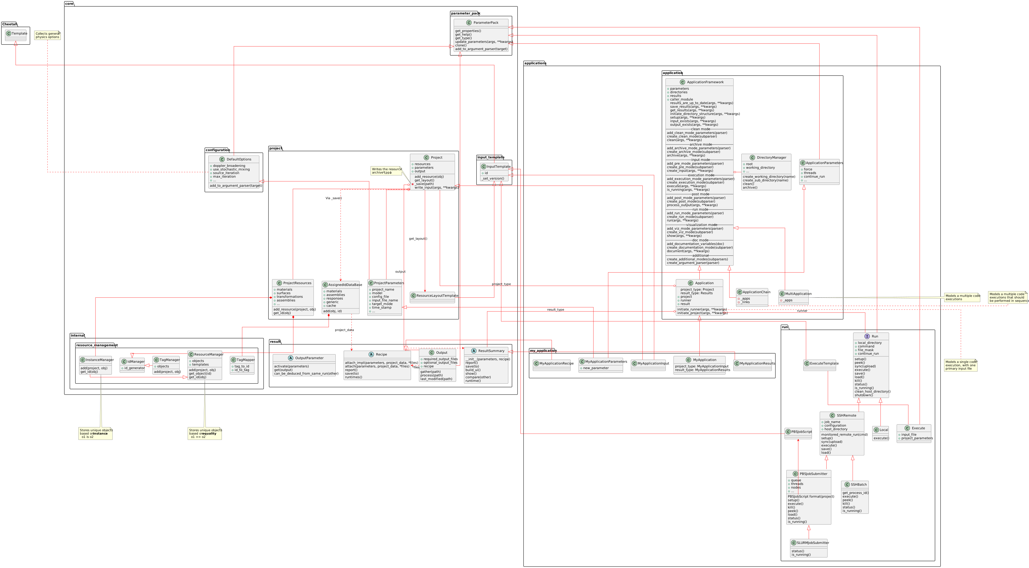
UML model of Rapyds Application Framework
Of course the application framework has to act upon a data model, which stores the actual reactor specifications in various classes, with their associated members and attributes.
This part of the system is termed the Rapyds Data Model, and is depicted in data_frame
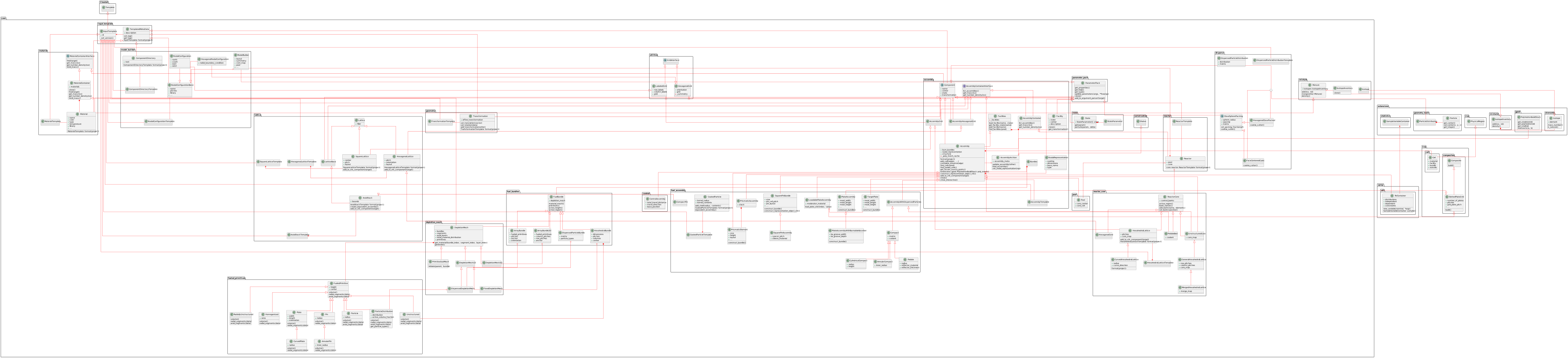
UML model of Rapyds Data Model
These figures contain a large amount of detail, most of which are not critical to cover at this stage. However, do note the major groups of classes, and their basic interaction with other class groups, as terminology from this diagram will be introduced and used in this manual.
Overview of the Rapyds Data Model
The Data Classes (from data_frame) describe the reactor. The full detail of the data model is not the focus of this manual, but an introduction is provided here for the sake
of completeness. Note that many of the statements below represent a “reading” of the diagram, meaning the sentence can be deduced from the relationships
described in the diagram.
CATEGORY |
MODULES/CLASSES |
ASSOCIATIONS |
|---|---|---|
General Classes |
Notable Base Classes |
Some important Rapyds base classes on which other elements build their behaviour |
|
the base class manages the way classes collect data and generically controls the way that class properties are set throughout the system. |
|
|
the base class defines the basic behaviour for any class which has a string representation, and potentially should be written out at some point to an input file for a code. This concept and terminology is related to the
Cheetah template engine which Rapyds uses to write out input files. In Cheetah the |
|
|
the base class of all reactor geometric components |
|
Reactor Data Elements |
Materials |
the set of classes which allow for the specification of homogeneous isotopic content needed to fill the reactor geometry. Looking at the UML diagram, we may note that: |
|
The |
|
|
a |
|
|
A |
|
A |
||
A |
||
Assemblies |
the set of classes which allow for the specification of geometric components of the reactor assemblies |
|
|
An |
|
An |
||
An |
||
An |
||
An |
||
An |
||
An |
||
Many specialisation of |
||
Burn Bundles |
The set of classes providing an independent material mesh structure for tracking burnable or activation region materials. This is an overlay mesh on top of the assembly geometry. |
|
|
A collection of |
|
|
||
|
||
For changes due to activation or burnup, fluxes are typically calculated on the |
||
There are options for certain complex/large geometries to redistribute the |
||
Reactor Core |
Set of classes which combine assemblies (or components) into a reactor core |
|
|
Set of classes which allow various forms of 2D lattice-based combinations of components to be created, such as |
|
A |
||
All lattices have an associated Template Class, to allow the lattice to written to the underlying codes. |
||
|
The |
|
|
The |
|
The |
||
The |
Although this table may seem rather obscure, it represent a direct reading of the UML diagram, and is presented here as example of how to interpret such a diagram. It further assist in introducing some terminology which will be of interest later in this training manual.
Overview of the Application Framework
The Application Classes (from application_frame) describe the interaction of Rapyds with external codes. Again, the full detail of the application framework is not the focus of this manual, but an introduction is provided here
primarily to define some basic concepts and terminology.
CATEGORY |
MODULES/CLASSES |
ASSOCIATIONS |
|---|---|---|
Application |
Application Classes |
Classes associated with a Rapyds application, which is a reactor analysis task at a code independent level |
|
The base application class, not often instantiated, but specialised into |
|
An |
||
An |
||
An |
||
|
A single standalone analysis application. A single code execution, with one primary input file |
|
|
Multiple independent analysis applications. Multiple input files to multiple codes all spawned simultaneously. |
|
|
Multiple sequenced analysis applications. Multiple input files to multiple codes all spawned sequentially. |
|
Project |
Project Classes |
Classes associated with a Rapyds project, which essentially puts together all elements to generate an input file for a calculation |
|
The base project class, identifying the |
|
|
Is a |
|
|
Collects the various elements (materials, surfaces, assemblies, …) of the input data |
|
|
Is an |
|
|
Is an |
|
|
An abstract class overriden per application to define how the generic output parameters to extract after the code run is complete. |
A large number of additional classes, beyond what is in the above UML diagrams or tables, exist in the Rapyds system, and can be inspected in the Rapyds system itself. For now however, we are more interested in the process of coupling a new external physics or engineering solver code to the Rapyds system, and seeing how to interact with the identified Rapyds classes to accomplsh this goal. The next section provides an introduction to this process, after which we will together go through such an example.
Introduction to Code Coupling
Coupling codes to the Rapyds platform requires work to be performed from four different perspectives. These are:
Work done as the Rapyds developer (RD). This step is not always needed, and depends on whether the application and Rapyds data elements needed for this work under consideration as yet exists in Rapyds at a code independent level. This step requires adaptation to existing, or creation of new Rapyds classes. For example, Rapyds already has an application for acritical casetype calculation, so if you simply wanted to add another code capable of doing this, this step can most likely be skipped.
Work done as the Plugin developer (PD). The Plugin is the connection between Rapyds and the external code, and contains primarily two components. Firstly, the template class which creates the input file/s for the external code, and Secondly the Recipe, which parses the output file from the external code. This role typically requires in-depth knowledge of the input and output files of the external code.
Work done as the External code developer (ED). The External code itself often may change or have updates made to it. This work may not be applicable if the external code you are intending to couple is outside of your control, or sufficiently featured for the task at-hand.
Work done as the Rapyds end-user (RU), meaning that a Rapyds input file must be created and the newly coupled code must be run to fulfil the intended purpose. This could include various modes of interaction with the Rapyds application, including generating the input for the external code, running the code, or post-processing the output.
Tip
Take note of these different roles discussed here, as the remainder of this manual will build on this separation of activities, and approach the problem from these four perspectives.